Xilinx FFT IP core 笔记
Posted on 2014-09-02 23:12 in IC
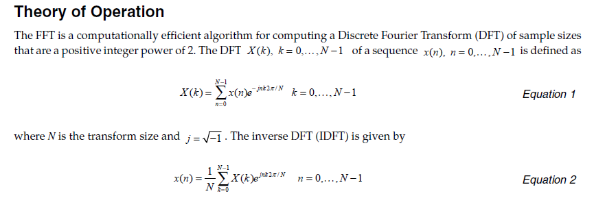
关于 FFT 的背景介绍就不再赘述,通原书和网上的教程、课件很多;关于这个 IP 核的介绍也就不再粘贴复制了,原版的 datasheet 必然是最全面的,仅记录我的使用时遇到的问题和需要注意到细节。
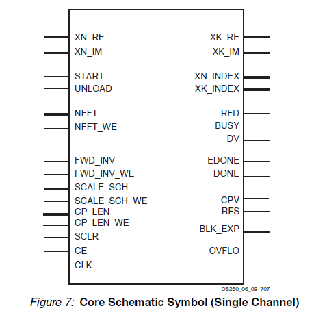
IP 核的接口示意图:
Timing
START / RFD port
datasheet 中没有专门描述 start 信号和其他信号的时序关系,只是简单介绍:
FFT start signal (Active High): START is asserted to begin the data loading and transform calculation (for the Burst I/O architectures). For Streaming I/O, START begins data loading, which proceeds directly to transform calculation and then data unloading.
在我最开始的测试小程序中,是先判断 rfd 信号,根据 rfd 来给 start 赋值。
思路是:首先必须等 IP core 准备好接收新数据时,才能开始
1 2 3 4 5 6 7 8 9 | |
但是仿真出来的结果显示 IP core 根本就没有工作,后来改了这两个信号的先后关系,
新思路:程序将输入 start 置有效,通知 IP core 需要调用,然后 IP core 根据自己的状态给出标识信号(rfd / busy),外部电路等到 rfd 有效时才输入需要变换的信号。
1 2 3 4 5 6 7 8 9 10 11 12 13 | |
这样子程序就可以正常运行了。
RFD / DV port
在 datasheet 中给出的时序图如下所示(Burst I/O Solutions with Natural Order Output)

实际仿真图:

实际仿真结果和示意图有一点点小差别:datasheet 中的时序图显示 rfd 必须在等 unload 阶段结束之后才能变有效,输入新的数据;但是实际的仿真图显示,在 unload 的后半段时间,rfd 已经变有效了,开始载入新的数据。
从理论上分析,采用 Burst I/O with Natural Order Output 方案,总共需要 3N 个时钟周期,load 阶段需要 N 个周期载入数据,processing 阶段需要 N 个时钟变换,unload 阶段需要 N 个周期来输出数据。
从仿真结果来看,unload 阶段和下一帧的 load 阶段有部分是重叠的,这样实际上的周期是少于 3N 个时钟的。
虽然功能上是不影响下一帧的数据的,毕竟和预期的时序不同,不知道是否会影响时序设计,有待继续观察。
Port
NFFT port
这个 FFT core 是可以设置为 动态重配置的,可以在运行时改变做运算的点数,非常方便,不过有一点需要注意到是重配置的点数是有范围限制的,比如我测试时设置的最大点数为 4096 点,那么运行重配置时,最小的点数为 64。可以选择 64 ~ 4096 之间的任何一个 2 的指数。
由于我一开始忽略了这一点,重配置为 16 点,迷糊了半天,重新打开 IP core 设置时才发现是自己看文档不够仔细 =.=
CP port
这个 FFT core 专门提供了一个端口可以设置循环前缀的长度,循环前缀 (cyclic prefix) 在通信中(尤其是 OFDM)是很有用的。
在向导中设置了 cyclic prefix insertion,并且在程序重配置时设置了 CP length = 10,但是仿真结果却没有出现 CP,和 CP = 0 时的结果相同。
仔细看了两遍程序和 datasheet,没有发现问题 ... 待解决!
Update 09/03/2014
又仔细看了两遍 datasheet,终于发现了原因所在。在关于 CP length 部分,最有一小段话一直被我匆匆忽略了:
The initial value and reset value of CP-LEN is 0 (no cyclic prefix). The core uses the log2(point size) MSBs of CP-LEN for the cyclic prefix length. So, when the point size decreases, the leftover LSBs are ignored. This effectively scales the cyclic prefix length with the point size, keeping them in approximately constant proportion. However, all bits of CP-LEN are latched into the core on CP-LEN-WE and are used in later transforms if the point size increases.
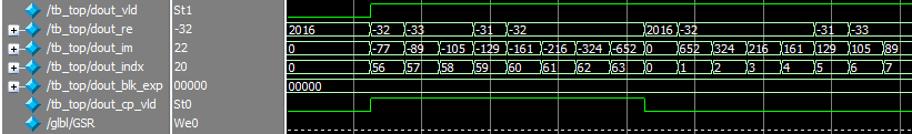
仔细读了一遍才明白,CP-LEN 起作用的是高位的数据 —— 从 MSB 起共 log2(point size) 位。比如我测试程序设置的最大点数为 4096,这是 CP-LEN 的位宽为 12 比特,但是在程序运行过程中,我重配置为 64 点,所以这时候应该从 CP-LEN 的最高位数起,共 log2(64) = 6 比特数据起作用。如果我想设置 CP 的长度为 8 点,则应该如下
1 | |
这时候,如下图所示,结果与预期相符。
FFT/ IFFT
在 FFT 的测试程序中,一切都正常工作,但是切换为 IFFT 模式,却出现了问题。
datasheet 中介绍,控制正反变换的信号一共有两个:fwd-inv 和 fwd-inv-we。前者取 1 时为 FFT,取 0 为 IFFT;后者是前者的写使能信号。
因为 FFT 的程序可以正常工作,说明程序逻辑是没有问题的。但是只配置这两个端口,就是有问题。自己研究无果,只能 Google,还真的找到以前有人也遇到同样的问题,并且给出了解决方法(不得不说,还是 Google 好,某度搜出来的结果都是广告和没有用的链接)
IFFT of FFT module does not work
IFFT in System Generator (blogspot 需翻墙 )
转原博客部分内容:
By default, the FFT block is configured to calculate DFT. The setup and timing of control/data signals for IDFT are the same as DFT except for two things:
The FFT block needs to be set up for IDFT by setting fwd-inv-we signal to 1 and fwd-inv signal to 0 before the start of the transform.
The FFT output needs to be manually scaled to account for the factor 1/N in Equation 2 above. The scaling can be done either by using the scaling schedule input or shifting the FFT output if the FFT block is set to "unscaled".
问题关键就在于第二条,需要手动设置数据缩放,给结果乘以 1/N。
原因就是这个 IP core 在计算 FFT 和 IFFT 时,利用两者表达式上的相似点,使用相同的结构,但是却缺少给 IFFT 的结果乘以 1/N 的步骤,需要用户自己添加。
在 datasheet 中介绍说
The inverse FFT (IFFT) is computed by conjugating the phase factors of the corresponding forward FFT.
但是却没有提到这个额外的 1/N 需要用户自己手动设置,应该算是 Xilinx 的坑。修正这个倍数关系以后,结果就与预期相符了~
(其实如果仔细分析对比 FPGA 和 Matlab 的结果,就能发现两者的差别就是这个 1/N 的倍数关系,只是自己对数字不敏感,又懒得仔细观察 =.=)
P.S. Test program
FFT IP core
设置
page1:
-
channel = 1
-
Transform Length = 4096
-
Radix-4, Burst I/O
-
run time configurable transform length
page2:
-
Fix Point
-
Input data width = 24
-
Phase factor width = 24
-
block floating point
-
natural output
-
cyclic prefix insertion
-
input data timing - no offset
page3:
-
use 3-multiplier structer
-
use CLB logic to implement butterfly arithmetic
运行时重配置
变换长度为 64 点,cp 长度为 10
Matlab
1 2 3 4 5 6 | |
Conclusion
FFT IP core 仿真结果:

对比 Matlab 中的结果,可以看到 IP core 的计算结果是正确的(除了 CP 的问题)。